![]()
![]()
![]()
![]()
![]()
![]()
![]()
![]()
![]()
![]()
![]()
![]()
![]()
![]()
![]()
|
|
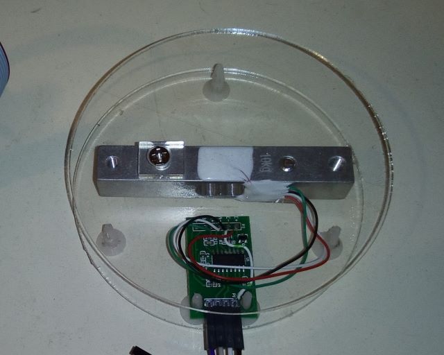
HX711 ADC and Load CellsThis is a basic 10Kg load cell kit. The kit came with:
Some assembly notes:The screws for the load cell are countersink type but the holes in the acrylic disks are straight drilled. It fits together much better if you countersink the holes. The mounting posts need 4mm holes, but the disks have 3mm holes. These need drilling out to 4mm, but this is difficult to do with a 4mm twist drill as the drill can snatch on the acrylic. The load cell has long connecting leads. Since I only intend to use the cell and PCB in the above "puck" configuration I shortened the leads on mine. If you plan to repurpose the cell later you might want to leave the leads at full length. From the top the colour sequence I used is red, black, white, green. The PCB really needs a 4 way right angle connector. I modified my connector by pushing up the pin to make it as long as possible then bend it over. The PCB has a small design error. The HX711 IC has two ground pins, one analogue ground and one digital ground. This is a common feature on ICs that combine analogue and digital functions on the same IC. These should be connected together, but the supplied PCB doesn't connect them. I added a link from E-minus to GND to correct this. Without this correction the IC will probably still work but an internal diode junction will be biased into conduction. Since the PCB seems to be readily available from several sources and I'm not reading a lot of reports of problems I assume it tolerates being used without the link. Communicating with the HX711Initially I'm using the supplied "readcount" function almost entirely as-is:
The function probably ought to return a signed long too, since you'll almost certainly want to subtract an offset to get a signed result. I'm also inclined to rename "Count" as it is misleading. I'd prefer "result". Dumping the reading gave me a value of around 8335700, and a 4 pound weight gave me 8700780. From this I determined a scale factor of 91,195/pound or 201100/Kg. Technically the interface is a sort of SPI, using CPOL=0,CPHA=1 and using the undefined state prior to the first clock as a "ready" flag. The device usually needs exactly 25 clock pulses though, and many hardware SPI implementations are limited to multiples of 8 bits. There is no "chip select" pin so if multiple HX711 parts are used they may need their own I/O pins. The number of clock pulses determines the next conversion type. 25 pulses means the A channel is read with a gain of 128. 26 pulses means the B channel is read with a gain of 32 and 27 pulses means the A channel is read with a gain of 64. A prolonged clock pulse of 60us or more puts the device into power-down mode. If you did wish to use the B channel for another load cell the reduction in gain isn't a great loss as the bottom bits of channel A are mostly noise. A note on load cellshttps://learn.sparkfun.com/tutorials/getting-started-with-load-cells I made some measurements of the resistance between wires of the load cell. Between red and black I measured 1K. Between white and green I measured 1K Between other wire pairs I measured 750 ohms. This is consistent with a bridge of 1K strain gauges with the red and black wires being the excitation (E+, E-) connections and the green and white wires being the measurement (A+, A-) connections. Historically measuring the output of a load cell required a sensitive amplifier as the resistance change is small, but converters such as the HX711 can be connected directly and the task of scaling the result can be performed digitally.
|