![]()
![]()
![]()
![]()
![]()
![]()
![]()
![]()
![]()
![]()
![]()
![]()
![]()
![]()
![]()
|
|
HD44780-based Alphanumeric LCDsLCD modules consisting of a display glass typically in a metal frame attached to a PCB equipped with one or more display driver ICs. These modules are a common choice for microcontroller projects They are readily available and cheap, however a number of variations exist. Note that the control IC used on the module has several software-compatible near-equivalents so even if the module does not have a HD44780 on it is likely to be a compatible equivalent. Typical display configurationsModules with only the controller IC
Modules with additional segment drivers
Historically the HD44100R 40 pin driver would support 8 characters, meaning a full size display implemented as per the datasheet would need 5 ICs: the controller and 4 expanders. More recent designs use HD66100F or equivalent 80 pin driver so only 3 ICs are needed. 4 line 40 character modules
Typical Pin-out for a single controller moduleA common arrangement is a single row of 14 pins or two rows of 7 pins using the odd-row, even-row pattern
An example of a Pin-out for a dual controller moduleModule type MC44005A6W, ERM4004-1 etc
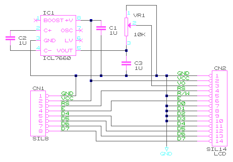
Pins 1 to 12 resemble the single controller version but in reverse order, however it isn't quite that simple due to the order of the power pins. In rare cases the display may include a voltage generator outputting a negative voltage on VEE, this is used to derive the supply for V0. The module I examined had a space for a SO8 IC U7 which would almost certainly be an ICL7660 or equivalent charge pump. This would allow a nominally 5V LCD "glass" to operate in a 3.3V system by allowing the contrast voltage to be up to twice the supply. A listing on Aliexpress showed a similar pin-out but with D0 on Pin 1. This is probably wrong but if this actually existed it would be convenient as it would allow a connector for 4 bit operation to be fitted starting from pin 5. Timing considerationsEnable has a minimum pulse width of 250ns (e.g. a 2MHz bus clock) RS and R/W are required to be valid before the rising edge of E D is only required to be valid in time for falling edge of E, though in microcontroller applications it is normally output earlier. Supply voltage considerationsIf the display has a PCB and metal display bezel it is likely that the display is designed for 5V. It appears as if most Chip-on-board alphanumeric displays are 5V. Chip-on glass type displays tend to be 3.3V. 5v Vcc display operation with a 5V microcontroller5v operation is the "default" for most modules, and on recent generations of LCD you can expect good contrast if you tie Vo to ground, though a resistor may be needed. One useful guideline I've seen is that if the user has the freedom to tilt the display then you may get away with fixed contrast, but if the display is in a fixed location the contrast should be adjustable. If you get a very faint display even with Vo grounded you may have a "extended temperature" type, these require a negative Vo. Display application data for an extended temperature type will often include a temperature-compensation circuit to automatically adjust Vo, though fixed voltage operation is also possible. 5v Vcc display operation with a 3.3V microcontrollerThe same contrast considerations apply. When powered from 5V the inputs of the HD44780U are compatible with 3.3V logic signals. This configuration is well suited to "write-only" applications. In configurations where it is required to read from the display it is important to note that the data pins may be driven above 3.3V so the microcontroller pins used must tolerate 5V from the display. 3.3v Vcc display operation of a 5v rated display moduleIf the module is intended for 5v operation then used as-is the 3.3v supply will give insufficient contrast. With Vo grounded the display text may be almost invisible. On the units I've seen if you get the light and angle right it is just about visible. The solution is to supply a negative contrast voltage. The key is that the contrast voltage supplied to the LCD is the difference between Vcc and Vo so if Vo is connected to -1.7v then the total contrast supply will be 5v, enough to properly operate the LCD. Vo is a relatively high impedance input and is well suited to powering from a charge-pump, typically an ICL7660 but due to the low loading a CMOS gate charge pump may be sufficient. It may be possible to program a microcontroller pin to output a square wave which could drive a charge pump.
Example of using a 5V LCD in a 3.3V design using the minimum 4 bit write-only interface. When using the ICL7660 on strip-board designs it may be worth removing pin 6 to enable the ground to run under the IC unbroken. This makes it easy to install a capacitor between GND and VOUT. Control from softwareThere is a choice of two connection methods, 4-bit or 8-bit, also you have the option of fixed timing or busy-polling. Most library code around tends to support 4-bit fixed timing, and it is often a good choice but not always. 4 bit modeIn 4 bit mode each byte is sent as two half-bytes, high bits first. This cuts down on the number of interface lines required. It is important to maintain synchronisation. On a successful clean power-on-reset the device will be in 8 bit mode, so initially we must send only the top half of the configuration command, then wait for completion. This will switch the display from 8 to 4 bit mode, but will latch garbage in the lower 4 bits. Once 4 bit mode is achieved then both halves of the command may be sent in order to properly configure it. I would advise against implementing reading from the display in 4 bit mode. While it is a supported feature my experience has been that the read function frequently loses synchronisation, meaning the high and low parts get swapped. 8 bit modeIn 8 bit mode all 8 data lines are used. This requires more interface lines but cuts down the number of I/O operations required. This mode might be used if there is already an 8-bit-wide peripheral in a system that can share the data lines. Alternatively if you are using an I/O expander there may be a benefit to using 8 bit mode to halve the number of operations required since a typical SPI/I2C expander implementation may require 32 clocks just to pulse the E line once. Fixed timing modeIn fixed timing mode the host microcontroller sends a command then waits a set time to allow the display to execute the command. Most operations are completed in 40us but the clear and home commands may take 1.6ms (these commands may be recognised as they both have the top six bits clear, so if (command and 0xfc) = 0 then wait), also it may be wise to allow 50us and 2.05ms to allow for slow displays. Many libraries implement this, as it is simple and works fine whether the display is connected or not. Unfortunately it can waste a lot of CPU time, particularly if the wait is implemented as a blocking delay. Timing in more detailIt is necessary to "read between the lines" of the datasheet to properly understand the timing. The command table gives delays for a 270kHz clock frequency, and with that frequency the command delay is 37us, and the long command delay is 1.52ms. The initialisation sequence uses delays of 4.1ms and 100us. If we assume that the delay is inversely proportional to the clock then it appears that the initialisation sequence assumes a worst case clock of 100kHz. This would seem remarkably low. I wouldn't expect a module clock to be less than 200kHz. If timing problems are observed then remember that it is not just the short instruction delay that needs scaling up, the long delay needs scaling up too. In my experience it is allowing insufficient time for a "clear" instruction that causes the most problems. In my designs it resulted in a blank display, probably due to a cut-off command being mistaken for display-off. A simple calculation gives the clock period as 3.7us, implying it takes 10 clock cycles to write one character. The clear delay appears to be 41 times longer, suggesting that a clear operation requires one horizontal "sweep" of the display. As a two line display has 80 characters of memory presumably it is erasing two characters at once. Busy poll modeIn busy poll mode the driver code reads the display's busy flag to determine if it is ready. This requires more work from the microcontroller, but may be preferable in some round-robin-poll applications where if the display is busy it can be skipped and other tasks executed. Polling appears unreliable in 4-bit mode. This may depend on specifics of the circuit in use, but in my experience synchronisation was lost frequently, and this resulted in incorrect BUSY status. Software initialisation sequenceThis is a special way to initialise the display from an unknown state. According to datasheets this is required if the power supply rise time is too long to satisfy the display's internal power on reset. It is also preferable on development boards where the microcontroller is frequently reset without cycling the power as this kind of reset leaves the display out of step. Probably the worst case scenario is that the display is already in 4 bit mode with half a command already latched. The initialisation sequence consists of sending the 8-bit-mode command repeatedly at set intervals to get the display into 8 bit mode. Then if 4 bit mode is desired then the top half of the 4 bit mode command can be set. The full sequence is:
* The datasheet assumes the worst case clock frequency of 100kHz. There isn't much to be gained by speeding up the 4.1ms delay but the 100us delay is actually just your normal write delay. ** this is a common catch, the display is still in 8 bit mode prior to this command so if you mistakenly try to send the full 8 bits as two 4-bit half-writes then the first would be interpreted as a command and the second as half of another command. After this last operation the busy flag will be valid and the display should return to normal execution times. After this you need to send normal initialisation e.g.
I would speculate that an improved reset sequence might be possible in which a dummy command 1111 is sent first. Since this can not be transformed into a "home" or "clear" command the extra long wait is not necessary. The following 0011 command should be sent twice but the 4.1ms wait should no longer be needed, avoiding the need for an "initialize display" function to block for over 4 milliseconds.
|