![]()
![]()
|
|
Data selector in Verilog and VHDLPractical considerations on file formats. VHDL has a more strict syntax than Verilog. Verilog has a "C-style" syntax and VHDL has a syntax of its own. A simple data selector will be implemented. It has three inputs A, B, SEL and one output Q. It is asynchronous, it has no clock. The truth table for Q might be written:
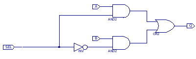
The project requires two significant source files, one constraint file and one logic file The constraint file describes how symbols map to physical IC pins. This is written in a language of its own, not VHDL and not Verilog. A peculiarity of FPGA projects is that the constraints file is not at the root of the project, instead it "belongs" to the top logic file. This seems odd, I believe that the constraints ought to be at the root of the project's hierarchy. That aside it is possible to implement the data selector in a schematic, VHDL or Verilog.A simple schematic is as follows:
In this version if SEL is zero the lower AND gate receives a one and it outputs B. If SEL is one then the upper AND gate receives a one and it outputs A. This simple design is subject to a race condition, if both A and B are true then switching between them will probably produce a glitch, which would typically be ignored. If the selector was used as a clock switch then a third term (A and B) could be added to eliminate this.A UCF file could be as follows:
Note that because the switches ground on the Elbert V2 every input ends up negated, though the outputs are wired as positive (on=true). Simulation and testing:It is desirable to simulate a logic design to ensure it complies with expected behavior. Tests can be written in Verilog though they are structured a little differently to source files. The ISE generates a template file, though it isn't as complete as the one I saw in an online tutorial. This confused me a bit but fortunately the tutorial had a link to the complete file.
This looks similar to a logic definition, but logic transitions are defined as happening at specific intervals, here denoted in nanoseconds. I do not know why the values are expressly cast as bits (1'b0 for false, 1'b1 for true) but this is how it was in the example I worked from. My test sequence isn't particularly efficient, but with three inputs the test could be brute-forced in 8 steps assuming we don't bother looking for race conditions. This simple design is subject to a race condition, if both A and B are true then switching between them will probably produce a glitch, which would typically be ignored. If the selector was used as a clock switch then a third term (A and B) could be added to eliminate this. This could be extended to check the outcome of each step with:
The strict equals operators ("===", "!==") are used in the test fixture so that we don't match on "don't care" or "undefined" or other quasi-logic states. The triple equals doesn't synthesize into logic but it allows us to test for the "Z" state.We still use the conventional operators in source files that need to synthesize to logic. This isn't quite like the situation in Javascript where "==" means "sort of looks like" and the triple equals operators are practically mandatory to suppress type type coercion. We can do better though using a "task". A task is similar to a procedure or macro, but it appears in sequence with the verilog code where it is invoked. This is different to modules that exist separately side by side. Using tasks we can rewrite our code to be a list of tests. I'm borrowing heavily from https://acg.cis.upenn.edu/milom/cis371-Spring12/lab/simulation/ as it is the clearest instruction I've found so far.
Notes: This is not and cannot be a generalized test framework as the task has to be rewritten if the number of inputs and outputs changes The '$display("The simulation is starting");' line looks redundant but I found that sometimes the test just doesn't run, so it is handy to have a line that just indicates that it started. I found that the reason the test didn't run is I ran the simulator on the source file and not the test fixture. It is an easy mistake to make. This test could be run against the Verilog version of the selector. A minimal Verilog data selector could be written as:
This uses the infamous Ternary operator "?" which is literally a "data selector" in code form. This introduces the concept of a Verilog "wire". A wire is a symbol that holds no state, it always evaluates to the expression assigned to it. The nearest C equivalent would probably be a macro: #define Q (SEL?A:B) but this isn't how we go about learning instead we look at the longer version:
This introduces some more important concepts, "reg" and an "always" block. Unlike wires a "reg" holds its state unless overwritten, usually in an "always" block. The "@" section gives the "sensitivity" of the block meaning the block only evaluates if a logic transition occurs in something it is sensitive to. Currently any input triggers an update so this behaves just like the assign version. An easy error to make in an "always" block is to inadvertently create a path that doesn't lead to the register being updated, causing it to hold its previous state. This mistake could be missed by the crude test shown above unless we go out of our way to code tests to look for sticky bits. In the test we see "reg" written to outside of an "always" but instead flow is controlled by time delays expressed using the "#". These do not synthesize into logic. This is horrible but also passes:
Meanwhile in VHDL
So the entity declaration looks a lot like a module declaration, and the architecture looks like its implementation. The word "Behavioral" appears to be just a name, but it serves as bookends around the process. The process looks a lot like an always block. Logic states do not equate to true and false so we must explicitly test them. VHDL currently does not have the Ternary operator so the minimal one line implementation isn't possible. A one line implementation of the selector is possible still:
|